


Room Automation v1.0
- dheerajgsr2020
- Sep 6, 2020
- 5 min read
When I started with the first version of this room automation project, my aim was to keep it very simple, but things got out if hand pretty quickly. In this first post, we will go through what the bare minimum of the project is but with complete with schematics and code snippets.
Overview:
As a proof of concept, I had it in mind to design a home automation system to control lights automatically based on data received on a PIR motion sensor and control the room's lights (two in this case) to turn it on when someone enters the room but also to be able to control them externally with the help of an IR remote.
The aim was to make it as non invasive as possible so that it can be removed at will and screwed on to the switchboard's outer plate when required. So this is completely removable and can be slapped back on in a few minutes which is the main focus of the project
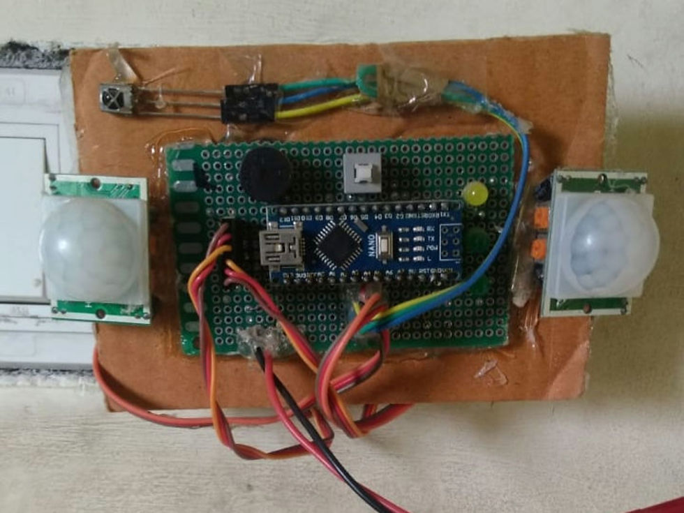
Components:
Beginning with the main board, an Arduino nano is at the brains of this operation.
Arduino nano
The Arduino nano was chosen based on these following parameters:
> Small footprint that would be ideal for the specific use case.
> Enough memory and computing power to handle even higher grade components should I ever chose to upgrade.
> Lastly cost effective when compared to other microcontrollers like the Teensy or ST boards.
PIR motion sensor
The sensors mainly include a PIR sensor aka Passive Infrared Sensor. Specifically the HC SR 501 module.
In this case, two PIR sensors at an angle to give better coverage. The PIR sensor is used in Repeat trigger mode which helps as it gives an output when the detected heat signature lies in the range of the sensor.
IR receiver.
An IR receiver, the TSOP1838 or IR sensor is also thrown in the mix just as a backup if anything goes off track, so as to be able to control it by an IR remote but proved to be a very useful sensor down the line.
Servos
Two servos are mounted to the back side of a mounting board to control the switches on the switchboard.
Besides these components, a buzzer and a few LEDs are also used for indications and to keep track of our commands to the device.
Schematic and circuit diagram:
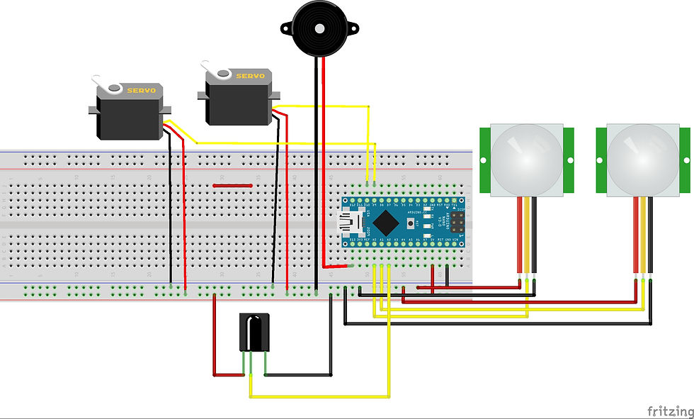
Starting with the sensors, the PIR sensors are connected to the analog pins A0 and A1. Next comes the IR receiver that is connected to the pin A2. These are the inputs to the Arduino. Now on the output side, we mainly have the servos that operate the switches on the switch board. These can be connected to any PWM pins on the Arduino, here they are connected to the pins D9 and D10. A buzzer is connected to the pin D13.
Working overview:
Initially the PIR sensor takes a few minutes to give us a stable reading, so for roughly five minutes, the device needs to boot up. And the servo is mounted in such a way that when it rotates it causes the switch to flip and turn the light on or off. After it is ready, a default servo that is pre-assigned in code will be controlled based on anyone being detected in the room. To change this, a mode button is assigned in the remote through which the user can choose between manual and automatic mode which means the user can choose if the PIR sensor changes the state of the servo or control it through the remote. To enable this, two buttons in the remote are put aside to turn the switches on or off. At any given time only one of the lights can be controlled by either the user or by the PIR sensor. To overcome this and turn both switches on, an SPDT push button in connected directly to the Arduino, which being triggered, will turn both switches on.
Code explanation:
The Arduino IDE allows the definition of a few constants beforehand so the code is clear and readable. In this specific code, on and off refer to specific angle value for the servos. The constants such as ON, OFF, MODE etc. are hexadecimal constants that the IR receiver sends to the Arduino when the corresponding buttons are pressed on the remote. The pin assignments and object definition have been done in the setup part of the program and have been skipped here to avoid complexity so that the logic of the program can be given attention.
Beginning with the servo control logic, there is a mean position(angle value) each for on or off. Considering the default state off as an example, the servo is set at a default off angle. When a state change occurs, the servo switches to an on angle but instead of stopping at the on angle, it slightly overshoots by 10 degrees to push the switch and then returns to the default on angle. This has been done so as to keep the on or off position of the servo at an angle that is less than the angle required to push the switch and hence at all times other than switching, the servos stay away from the switch and prevent unwanted load on the servos. This is part of a function called lampSel(char lamp, int degrees) which is used further in the code.
  if(state == on)
    {
      servo.write(on + 10);
      delay(250);
      servo.write(on);
      delay(250);
    }
    else if (state == off)
    {
      servo.write(off - 10);
      delay(250);
      servo.write(off);
      delay(250);
    }
Now for the IR sensor, the IRRemote library is used and that is processed with the PIR sensor data so that the user can switch between telling the device to use PIR sensor or the IR remote data which is kept track of in the code through a 'mode' variable. The push of any button on the remote by the user would assert the mode variable and complete control would be given to the user.
The mode variable is 0 when PIR sensors are used as input and 1 when the IR receiver is used. Here x and y are the readings of the PIR sensor. This value will be a 1 when the PIR sensor detects a heat signature and 0 otherwise.
To change the switch that the code accesses, a function lampSwitch() is used simply to switch between the two servos that are being controlled.
    x = digitalRead(pir_sensor1);
    y = digitalRead(pir_sensor2);

      if (mode == 0)                           //PIR senors as input
      {
         if (x == 1 || y == 1)                 //When PIR sensor
         {                                     //detects anything
            lampSel(lamp, on);
         }
          else if (x == 0 && y == 0)           //If PIR detects nothing
         {
           lampSel(lamp, off);
         }
     }

     else if (mode == 1)                       //IR remote as input
     {
        if (irrecv.decode(&results))           //Switch b/w lamps
        {
           if (results.value == LAMPSWITCH)
             lampswitch();
        }
        else if (results.value == MODE)       //Change mode to PIR
        {                                     //control
           mode = 0;
           digitalWrite(mod, HIGH);
        }
         else if (results.value == ON)        // Turn ON lamp
        {
            mode = 1;
            lampSel(lamp, on);
        }
         else if (results.value == OFF)      // Turn OFF lamp
        {
            mode = 1;
            lampSel(lamp, off);
        }
        irrecv.resume();
        delay(30);
    }
Power management tips:
Initially the whole project was powered by a 5V 500mA supply. But soon when the number of servos was increased, clearly the project drew a bit more. Finally a 5V 1A supply seemed to work fine. The Arduino gets its power through the Vin pin so that the regulator on the Arduino board can let the MCU have a near constant power supply even when the servos draw a considerable amount of current. Further a 100µF capacitor can be connected across the input of Arduino to help in managing power surges.


Excellent work u should work at Spacex. Hey Elon hire him