


Project Lucy Mk1: The dive into it
- dheerajgsr2020
- Apr 21, 2021
- 8 min read
So if you guys have been following along, this is the blog where I go on a bit of a technical rant about Project Lucy Mk 1. For this particular project, I went all out designing my own PCBs, new microcontroller, a 2.4 inch touchscreen TFT LCD display and just about everything on the code part of things. Now this is the blog where I will be discussing about the functioning and inner workings so let's just dive into what's under the hood.
Core and the sensors.
Project Lucy Mk1 has a Teensy 3.2 microcontroller that's got an Arm Cortex-M4 at 72 MHz which makes it quite zippy compared to the Arduino BUT its got a heavy price-tag. The microcontroller also has a RTC(real time clock) built in which was put to good use as you shall see.
On the sensors side of things, there has not really been much of an upgrade from my previous versions and I'm still sticking with PIR sensors for human detection and on the voice side of things, it's the same too so at this point, if you wish to know more, feel free to check out my other blogs where it's all in a but more detail.
The only addition for this version is the addition of LDRs which serve the purpose of detecting if the room is too bright for turning on the lights when I enter.
The "how to control lights" part
Now to tackle a specific problem that persisted ever since version 1 is the non-invasive technique, I have had to come up with a few creative solutions before. But this time I have gone down the conventional route of using relays but I have added a failsafe just in case a relay would fail. So any relay is a 2 way switch. When most use it, they only use one common pin and a Normally open (NO) pin. But instead my ideal way of using it would be something of this sort. Since it already is a 2-way switch in itself, why not use another 'actual' 2-way switch on the other side so other than the relay, there is still a method of turning the lights ON or OFF. What made my work even simpler was the lamps that I wanted to control had a 2-way switch before so a relay was just a drop in replacement.
But even then, if the lights are on through the relay and the switch was pushed, it would turn the lights off but now, logic inverted, when the relay turns off, the lights turn on, and similarly the other way. So the microcontroller needed some feedback about the information of the switch position in order to flip the relay to the right position where it really does turn the light on.
To tackle this issue, I had to come up with a sensor setup of my own and when I couldn't find the right combination of the sensors, being the guy I am, I just made that sensor myself.
IR position detection:

Coming to this sensor, this is just an IR distance sensor that is clamped, by the resistor values, to go off at a particular distance which is the distance between the switch bottom and the sensor. Like in the image above, it sits below the switch and when switch is in its OFF position, IR rays are reflected back into the sensor by the bottom of the switch and are detected, but when it is in the ON position, no light is reflected and hence cannot be detected. This is a crude explanation of this sensor design. In another blog dedicated to the sensor, I will discuss the specifics of the LEDs used, the op-amp used and the whole thought process behind it's development.
User Interface
This is mostly code , just concepts not actual code so hopefully this will save me some trouble of including this is the code section.
So for the most effective use of a 2.4 inch touchscreen, it was obvious that a menu system would be most efficient in handling output and input. Instead of explaining, I have put together this flow diagram that shows the various menus and sub-menus and their functionalities.
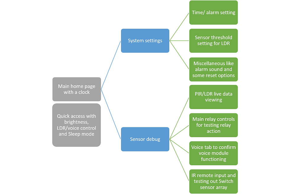
The main home page consists of a clock display that displays date and time obviously, and also has a quick access menu that controls the brightness of the LCD display and has toggle switched to turn ON or OFF the LDR and Voice module so those functionalities can be disabled when I wish. The main reason being false triggering. If I'm on a call in my room, it catches random stuff and takes it as a command so it really bugs me when I'm talking on the phone and my lights go brrr....
There is a sleep button also whose functionality I will get to in a part further in this blog.
After that main page, there is an authentication page to make sure no random baby be messing with my room beyond which is the menu of System settings and sensor debug. The system settings is self explanatory, stuff like time, date, alarms, LDR threshold that kind of stuff can be configured here.
LDR threshold is a value which if the real time value exceeds would not cause the lights to turn on even when I enter the room. It basically decides the point of minimum brightness I want in my room.
So at the sensor debug sub-menu, there are various fields where I can go in and look at the real-time
data coming from a sensor, check if any sensor is acting strange, check if relays are okay through toggle switches on the touchscreen and that kinda stuff. So in all of my previous versions, in case of any sensor messing up, I had to remove it, get a multimeter and probe its outputs but now all this is programmed into the system.
RTC functions
An RTC(real time clock) keeps track of date and time that have to be set for once in the microcontroller and unless there's power in the system, that clock will be running and will keep track of date and time. So in the Teensy 3.2 there is a separate pin called VBAT that is a battery input which if hooked up keeps the RTC running even when power to the whole microcontroller is removed, so in a way a backup if you want to call it that.
The RTC has mainly 2 functions in this project, one is understandably to display date and time in the home page of the menu but the other is the most intriguing one.
So the RTC can also be used to trigger alarms and this must be the fanciest of them all. Since Lucy has controls of my lights, I can set a morning alarm in the system settings, also turn on alarm sound and go to sleep, also put Lucy to sleep through the sleep button in quick access. When its morning, an alarm goes off with the usual beep-beep but if I do not turn it off, all the lights in my room turn on making me get up, press the snooze button for at least 10 seconds and then the alarm goes off making sure I wake well up by the time I turn it off.
The alarm uses a timer to the set time so the RTC needs the amount of time it needs to sleep for and not the time at which it needs to wake up. Pretty convenient time in 24 hour format is a value along a continuous circle for which taking a circular difference would solve it.
Sleep modes:
Lucy has an active wake mode and 2 sleep modes, one is hibernate mode and the other is deep sleep.
From the active wake mode Lucy can go to a deep sleep mode where power consumption would be under 5mA, all peripherals and sensors will be turned off and this is the mode where Lucy will wait for the active alarms. Once in sleep, I can hit the snooze button once to put Lucy into hibernate mode where no peripherals will be activated but time can be viewed by screen in minimum brightness, basically for when I wake up at night and wish to see the time. In hibernate mode, there are only 2 options, either wake Lucy up completely from sleep or to put Lucy back into deep sleep. This is a weird program branching for an infinite loop based microcontroller program and will be discussed.
Circuit and PCB design:
For Project Lucy, I had to design 2 different PCBs, one for the Switch position sensor and another which is the main board. The IR switch position sensor is a single layer PCB that has the IR transmitting and detecting LEDs, op-amps and some resistors out of which the LEDs are the only THT (through hole technology) components whereas the resistors are SMD 0805 package number and the op-amp is SOIC-8 package. All these SMD components were hand soldered using a 35W soldering iron.
The main board consists of the microcontroller and display obviously, connectors for the sensors, transistors and MOSFETs for controlling power to the sensors in deep sleep mode, snooze button, buzzer, bypass capacitors, base resistors and other passive components all in THT packaging only. Not that I could not solder SMD components but due to availability reasons, I only had one shot at assembling the board so making it SMD was not worth the risk.
Here are the schematic and PCB silkscreen for the readers.


Code:
There are three main functions, one to handle display, one to handle input from touchscreen or sensors, and the other is a recursive function to handle sleep. The function does either a recursive call or not based on what option is selected when in hibernate mode. The input function runs perpetually as the system is always listening for input be it user input from touchscreen or sensor input. The display function runs only when the display is being updated. In a screen update cycle, the display first clears the screen, in other words paints it black, then puts the image of the menu and then hands off its control to the input function that waits for an input from the touchscreen. This is done so as the LCD talks through SPI communication, the data going to the display and input data coming from the display use the same data bus and hence cannot be operated simultaneously.
In the man loop, the input function is perpetually running along with the basic functionality of handling the lights but this time with additional branching thanks to the LDR route. Also in this loop any user input in the form of voice commands or IR remote inputs (yes, the IR remote is still a thing and I'm not giving it up just yet) and those are processed just as in previous versions so not much to see here. That is how simple the code is. What makes it complicated is the menu part which I have executed in a very crude manner as my use case is quite limited, there exists libraries for the Arduino that make the implementation much more straight-forward but do not provide the level of control I need and that's why I designed the menu branching from the ground up.
After final assembly:


Conclusion:
What else can I say other than "This has been one hell of a ride" ?. This is the most professional looking thing I have ever designed and is at the same time, the most complicated project spanning for well over a year, that year being the most stressful time of 2nd PUC or 12th grade. If I were to do it again, I would not do it at all because it's not even been 3 months since it's completion and instead of upgrading like previous versions, I am designing a new one Project Lucy Mk3, yup skipped 2. This might well be a project that I would fall back to if in case the new version is compromised because, spoiler alert, the new version will have networking capabilities as well.


Comments